

Ansys Modal

In this tutorial, we will learn the basics of how to create a simple modal analysis in Ansys Mechanical.
Modal analysis is used to find the natural frequencies and mode shapes of a body under given boundary conditions.
-
Step 1: Get started

Open Ansys workbench and drag and drop the modal analysis tool in the project schematic.
-
Step 2: Material Data

This step is optional, but if you wish to use any material other than the default structural steel, then you can either select that material from the Ansys material library or create your own material by entering data like Young's Modulus, Poisson's Ratio, Density, etc.
-
Step 3: Geometry

You have an option of importing the body or constructing it in Ansys. If you wish to construct it in Ansys, I recommend you do it in Design Modeler.

For this problem, we will use a cantilever beam of dimensions 2X0.1X0.1 mm. Sketch it on a plane and use general constraints to define it's dimensions.

Click on modeling and go to create->extrude. Select the sketch and click add. Define the length and click on generate.
Once the model is complete, close Design Modeler.
-
Step 4: Meshing
Click on Model.

Right click on meshing and select insert->sizing. Select the body and enter the edge length of individual elements. We will used 0.05 m for this example. Since this body has a very simple geometry, we won't need any complex meshing tools. Right click on mesh again and click generate.


This step is not required for this problem, but you can check the quality of a mesh by clicking on mesh->quality->mesh metric->aspect ratio. Aspect ratio is the ratio of the maximum distance between the centroid of an element and the centroid of any one of its sides to the minimum distance between the centroid of the same element and the centroid of any one of its sides. Typically, a maximum aspect ratio below 10 is ideal. Since all elements produced in this problem are perfect cubes, the aspect ratio is 1. For analysis like CFD, other mesh metrics, like SKewness, are prefered.
-
Step 5: Boundary Conditions

For this modal analysis, we only need to define the fixed support as so. Right click on Modal (A5)->Insert->Fixed Supports, select the face and click ok.

Go to analysis settings and define no.of mode shapes. For this analysis, we will select 3 mode shapes.
-
Step 6: Solution

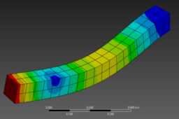
Right click on solutions, click on insert->deformation->total deformation. Click solve.

Right click on total deformation and click on create results at all sets. Click on solve. You will get deformation at all mode shapes.
Feel free to message me in case of any queries.
THANK YOU
